
Antenna Modeling without Breaking the Bank
- Bill Powell

- Jan 29
- 4 min read
One of the most important components of an Amateur Radio station is the antenna. Many aspects must be considered before deciding on the best antenna for one's particular situation.
What frequency will it be used for?
How much space can be allocated for the antenna?
How much power will be input to it?
How much gain do I need/want?
Should it be directional or omni-directional?
How much would a commercially-made antenna cost?
Will the antenna be mounted permanently or portable?
What modes will be worked using the antenna?
There are other considerations, but these are things to think about before putting an antenna in the air. In this article I will briefly address these topics while presenting a way to model an antenna that you could build yourself rather than purchase it. The great thing is that you can build it for very low cost and reduced frustration by using parts available at the Shack and other facility resources. An added benefit is there are other experienced Hams to help you out if you encounter something you need assistance with. In the end you would have an antenna that you built yourself and will meet your needs as you defined them.

Before you decide that modeling is too difficult and involves a lot of mathematics, let me tell you, if you have the proper tools the process is a lot simpler than you might think. And there is very little math involved in modeling nowadays. Modeling software has become more readily available in the past few years, for the right price (free), and you don't have to have a math degree to model some very complex antennas.
In the past there were complex and expensive modeling applications based on the NEC (Numerical Electromagnetic Code) computing engines. EZNEC was and still is a popular software program used to model, analyze, and design antennas by simulating their performance. EZNEC uses the NEC-2 or NEC-4 engines tocompute current distribution and radiation patterns. The NEC-2 version is now free which allows DIY'ers to do modeling without breaking the bank. The NEC-4 version still has a license fee, but for casual users like us Hams, the increased accuracy is not that much better than results from the NEC-2 version.
Another free application is MMANA-GAL which is popular in Europe. A PRO version is also available.

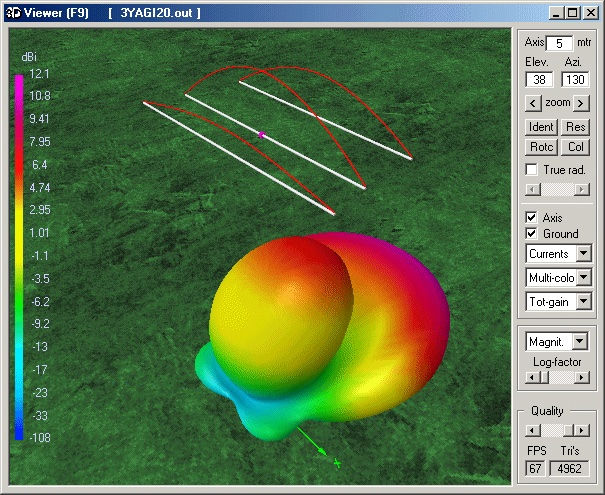
Yet another option is to use an application called 4NEC2 which is also free and a bit simpler to learn (in my opinion). An image of the Main window for the application is shown below. 4NEC2 is a completely free NEC-2, NEC-4, and Windows based tool for creating, viewing, optimizing and checking 2D and 3D antenna geometries. It also generates, displays, and compares near and far field radiation patterns. 4NEC2 is for both beginning and experienced antenna modelers. You can use 4NEC2 to model simple antennas like verticals and dipoles. You can model more complex antennas like Yagis, and very complex antenna systems like stacked Yagi arrays. Many other antenna types can be modeled.
One of the most important features of 4NEC2 is the ability to optimize and antenna parameters.

You don't have to construct an antenna, put it up, test it, take it down, adjust it, put it back up, and test it over and over. You can model it and optimize it before putting it up even once. After you build it and put it in the air, you may not have to take it down if the actual performance is close to what the simulation showed you and what you want.
Before taking on the actual modeling, I recommend reading an article published in the November 2000 issue of QST magazine. It is the first in a series of four articles by L.B. Cebik, W4RNL.
Here's a link to the Part 1 article A Beginner's Guide to Modeling with NEC:
One topic covered in the article you may not be familiar with is that of segments. Pay attention to the Language of Modeling part of the article, and especially the coverage of segments.
Also important is to have a pretty good understanding of 3 dimensional visualization (X, Y, and Z positions). I find it useful to think of X running East to West, Y running North to South, and Z being the height above ground.
In modeling using 4NEC2, a feed point of the antenna being modeled is called the source.
Another bit of information to think about is that the application does not consider items near the planned installation such as a house, metal roof, garage, other antennas, etc. These may affect the actual behavior of the antenna.
I am planning to do a follow-on article in which I describe how to model a simple dipole antenna for 75 meters using the 4NEC2 application. If there is enough interest I will create another article covering how to model a UHF Yagi antenna.
Please let me know what you think. Are you ready to try your hand at modeling the perfect antenna for your situation?


Comments